Term of the Moment
GPT-5
Definition: Boolean gates
The Boolean logic gates AND, OR and NOT comprise transistors, which are on/off switches wired together. Gates have one or two inputs but only one output, and they are wired in patterns that make up electronic circuits.

Transistors in Series

Transistors in Parallel

An Inverter
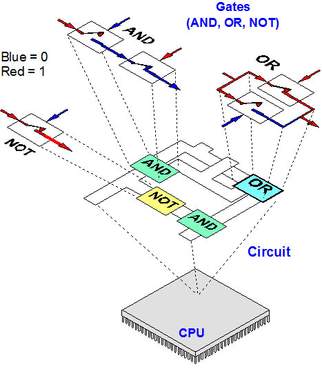
From Gates to Systems
In this AND example, both inputs have no pulses of electricity (both are 0). In order to trigger both transistors to close and allow the source current to flow to the output, both inputs must be pulsed.
In this OR example, any of the two inputs will trigger their respective transistor to close, and the source current reaches the output side.
A NOT gate is conductive in its normal state. When pulsed, the transistor opens and impedes the current.
Boolean gates make up circuits, and circuits make up electronic systems. This circuit adds two bits together (for details, see Boolean logic).